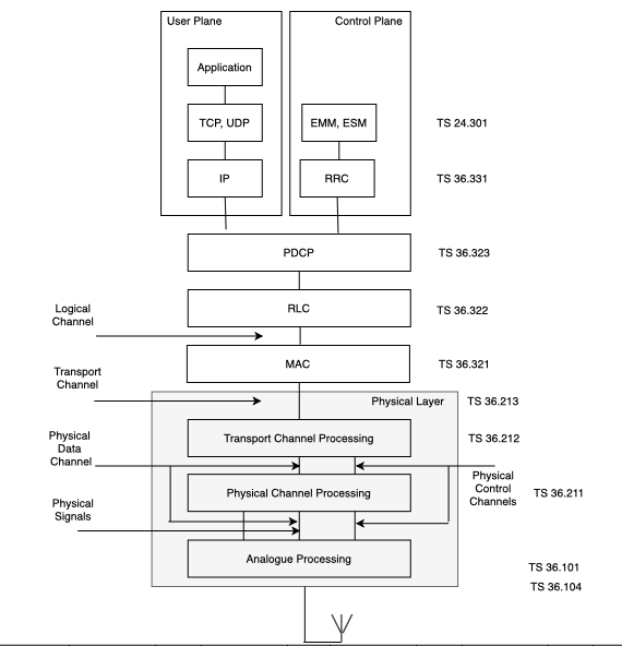
The above is control plane architecture of LTE.
If you observe the “NAS” layer is there UE and MME. “NAS” layer is not present in eNB. But for the NAS messages to be reached to UE from MME, there is no direct message transfer between UE and MME.
THe NAS messages should go through eNB.
“RRC” layer is present in UE and eNB. Hence “NAS” layer messages are transferred using “RRC” layer.
This concept is called as Piggybacked Concept.
The process of including one layer message in another layer is called as Piggybacked concept.
We shall see with the help of examples:
RRC : RRC Connection Setup Complete + NAS : Attach Request + ESM : PDN Connectivity Request
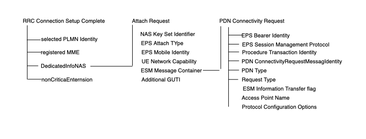
In the “RRC Connection Setup Complete”, it has 4 IE.
Inside “DedicatedInfoNAS” IE “AttachRequest” is present. So we can say that, “AttachRequest” is piggybacked inside “DedicatedInfoNAS” IE.
Now inside “ESM Message Container”, “PDN COnnectivity Request” is present.
RRC : RRC Connection Reconfiguration + NAS : Attach Accept + NAS : Activate Default EPS Bearer Context Request
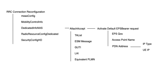
Here also inside “DedicatedInoNAS” IE, “AttachAccept” and “Activate Default EPS Bearer Request” message is present.
RRC : RRC Connection Reconfiguration Complete + NAS : AttachComplete + ESM : Activate Default EPS Bearer Context Accept
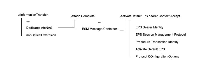
Here also inside “DedicatedInoNAS” IE, “AttachComplete” message is present.
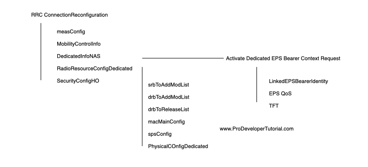
RRC : RRC Connection Reconfiguration + NAS : Activate Dedicated EPS Bearer Context Request